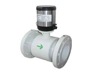
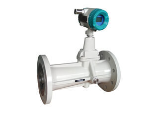
Partially filled electromagnetic flow meter introduction
Pipeline electromagnetic flowmeters are usually applied to full pipe flow of liquid in closed pipes. For the case where the flow rate changes greatly, the liquid sometimes fills the pipeline, and sometimes the pipeline is not full, the pipeline electromagnetic flowmeter cannot be applied. If weirs or submersible electromagnetic flowmeters measuring open channel flow are used, the head loss when the pipe is full is too large, affecting the outflow; if the flow rate is too small, the fluid cannot enter the weir or submersible electromagnetic flow sensor and cannot be measured. The non-full pipe electromagnetic flow sensor can be consistent with the installation pipe diameter and work in a large flow range. It can be used to measure the full surface flow of closed pipes and the free surface flow of non-closed pipes or open pipes without causing head loss, such as Municipal drainage wastewater treatment Agricultural irrigation fluids are measured by natural downflow.
The electromagnetic flowmeter is based on the constant cross-sectional area of the sensor, and the average flow rate is measured to obtain the flow rate. The cross-sectional area of the fluid in the non-full pipe is variable. The flow measurement not only measures the average flow rate through the sensor, but also measures the cross-sectional area of the fluid through the sensor. That is to say, at least two variables of flow rate and liquid level are required for the flow measurement of the non-full tube electromagnetic flowmeter.
According to the weight function theory, the signal voltage induced on the electrode is the collection of all particle potentials in the electrode cross section. In a non-full tube sensor, no matter how the cross section of the water changes, the particles of the fluid flow will always have an induced potential, which should be within the collection range of the electrode. The electrode should not be exposed to air, otherwise the electrode will not get the induced flow signal. Therefore, in the structure of the non-full tube sensor, there are (a) a large-area electrode with the center of the tube biased toward the bottom as shown in the figure below; (b) a multi-electrode shown; (c) a liquid level detection point installed at the bottom of the sensor Electrode and other structures.
In the non-full pipeline sensor, the flow velocity distribution is determined by the hydraulic gradient of the pipeline, and the measured average flow velocity must be corrected for different flow velocity distributions. When W × B = constant is satisfied, the measurement is not affected by the change in flow velocity distribution, and W is related to the electrode area and the geometric position of the particle. In non-full pipeline sensors, different fluid cross-sections change the geometric position of the particle potential and the electrode area, that is, change the weight function W. Some types of non-full-tube sensors can change the magnetic induction intensity B through a special form of excitation to sense different electromotive forces to obtain the water level.
In non-full pipeline electromagnetic flowmeters, there are many methods for measuring the liquid level. Most of them do not add a liquid level sensor, but the liquid level measurement is completed by a flow measurement electrode or a liquid level detection electrode in the measurement tube lining. Common methods for measuring liquid level are as follows:
Applying the principle that the weight function is related to the geometric position, using two different excitation coil connection methods, changing the ratio of the electric potential generated by the magnetic field, establishing the functional relationship of the liquid level, and calculating the liquid level through the single-chip calculation.
Application of capacitance method for liquid level measurement. Capacitance measurement is based on measuring the capacitance between two metal plates arranged in the liner of the measuring tube in proportion to the cross-sectional area of the fluid to measure different liquid levels.
The flow measurement of the non-full tube electromagnetic flowmeter requires complex calculation and control of the measured electromotive force and excitation, and its development is obviously inseparable from the development of single-chip microcomputer and computing technology.


.jpg)

.jpg)
.jpg)
.jpg)
.jpg)
.jpg)
.jpg)
.jpg)
.jpg)
.jpg)
.jpg)
.jpg)

.jpg)
.png)
.jpg)
.png)