Metal Tube Rotameter Troubleshoot
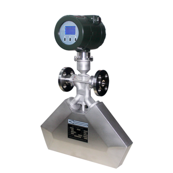
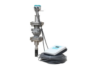
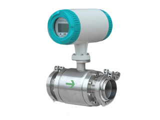
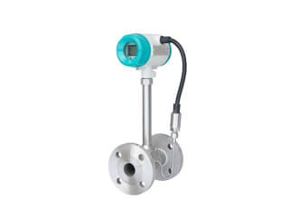
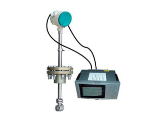
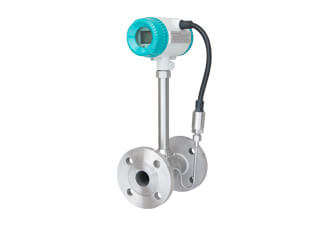
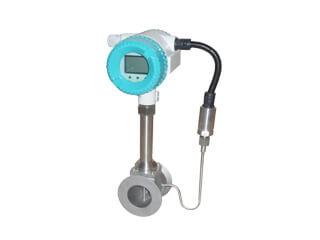
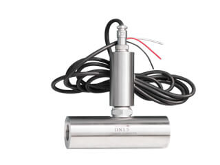
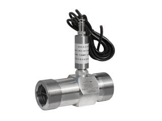
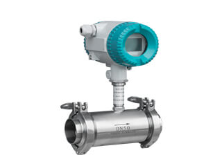
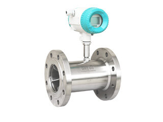
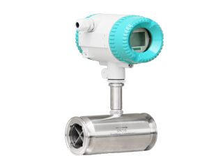
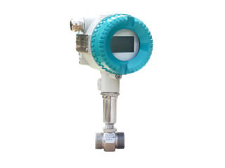
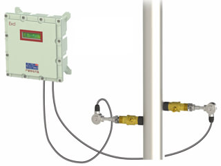
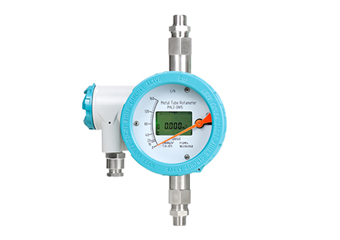
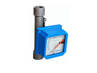
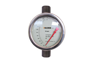
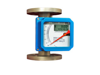
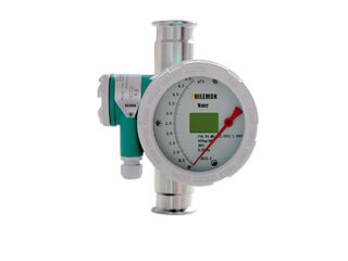
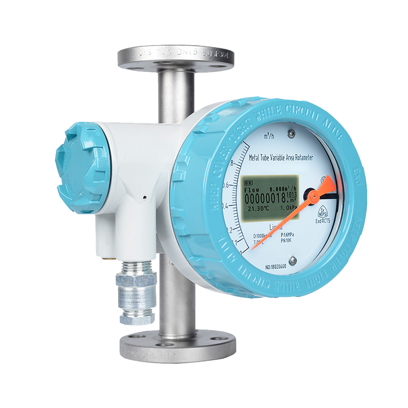
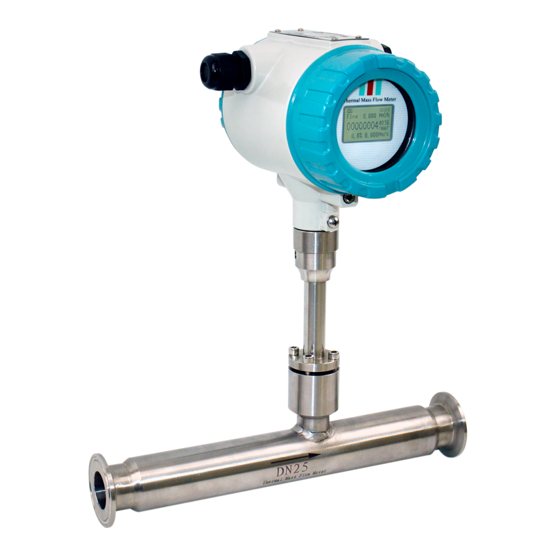
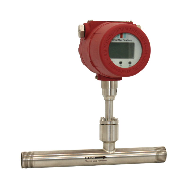
metal tube float flowmeter is used to measure the flow of liquid, gas or steam in the closed pipeline. It is widely used in process control and is especially suitable for the control and measurement of small and medium flow. It consists of a cone, a float, an indicator, and a converter. When the fluid flows into the cone float, and the lift M is balanced with the gravity G, the displacement of the float is transmitted to the indicator by the magnetic steel to indicate the flow in situ or converted into a corresponding electrical signal by the converter.
Q & T instrument specialize in the production of electromagnetic flowmeters, orifice flowmeters, vortex flowmeters, metal tube floats and other flowmeters. Below are the common faults of metal tube float flowmeters. Based on past work experience and combined with the feedback information of our customers, we have carried out one-to-one analysis and found out the corresponding solutions, hoping to bring convenience to everyone.
First, pointer jitter
Slight jitter: Generally caused by media fluctuations. The problem of increasing damping can be used to solve the problem.
Moderate jitter: Generally caused by unstable media flow conditions. For gases, it is generally caused by unstable operating pressure of the medium. A steady or steady flow device can be used to solve or increase the air damping of the metal tube float flow meter.
Severe jitter: mainly due to medium pulsation, air pressure instability or pressure, temperature, flow rate of the gas operating state given by the user and the actual state of the float flowmeter, resulting in the metal tube float flowmeter exceeding the range.
Second, the pointer stops at a certain position and does not move
The main reason may be that the float of the metal tube float flow meter is stuck. Generally, when the metal tube float flowmeter is used, the valve is opened too fast, so that the float quickly impacts the stopper upward, causing the stopper to deform and the float to be stuck. However, it is not excluded that the float is stuck due to the difference between the float guide rod and the stop ring. When handling, please refer to the instruction manual to remove the instrument, remove the deformed stopper and shape it, and check whether it is concentric with the guide rod. If it is different, you can correct it, then install the float, push the float back and forth, and feel the float up and down. No obvious friction. In addition, when the float flowmeter is installed, it must be installed vertically or horizontally, and it cannot be tilted. Otherwise, it may easily cause the card table and bring errors to the measurement.
Third, the measurement error is large
1. Installation does not meet the requirements
Install the metal tube float flowmeter as far as possible to maintain vertical or horizontal, the inclination angle is not more than 20 degrees; there should be no ferromagnetic objects in the 0.5 meter space around the float flowmeter; the installation position of the flowmeter should be away from the valve variable diameter port, pump outlet, process pipeline turn Oral; to maintain the requirements of the 250mm straight pipe section after the first 5D.
2. The density of the liquid medium changes greatly
Since the instrument is converted according to the density given by the user before the calibration, the flow rate of the water in the calibration state is calibrated. Therefore, if the density of the medium changes greatly, the measurement will cause a large error. The solution can bring the density of the medium after the change into the formula, convert it into the error correction coefficient, and then multiply the flow measured by the flow meter by the coefficient to convert it into the real flow.
3. Since the gas medium is greatly affected by temperature and pressure, it is recommended to use temperature and pressure compensation to obtain the true flow rate.
4. Due to many factors such as long-term use and pipeline vibration, the floating flowmeter senses magnetic steel, pointer, counterweight, rotating magnetic steel and other moving parts loose, resulting in large errors.
It can be verified by pushing the pointer by hand. First press the pointer to the RP position to see if the output is 4 mA, the flow display is 0, and then verify according to the scale. If the discrepancies are found, the instrument components can be positionally adjusted. Generally, professionals are required to make adjustments. Otherwise, the position may be lost and return to the factory for calibration.
Fourth, no current output
First look at the wiring is correct.
Whether the LCD has a display, if there is no output on the display, the output tube is mostly broken, and the circuit board needs to be replaced.
Missing calibration value. Due to the failure of the E2PROM, the meter calibration data is lost, and there is no output current, and the current will remain unchanged. Solution: Data recovery operation can be used. If it does not work, you can set the data in password 2000 first, and then set the data in password 4011 by pushing the pointer to calibrate the data from RP to 100%.
Fifth, no online display
Check that the wiring is correct.
Check that the power supply is correct.
Reinstall the LCD module and check that the contact is not correct.
Check whether the 12 and 13 terminals are connected to the ammeter or short circuit for the multi-wire power supply mode.
Sixth, the on-site LCD meter always shows 0 or full scale
Check the set range and zero point parameters in the 2000 password. ZERO is required to be less than the value of SPAN, and the two values cannot be equal.
Check whether the sampled data is up, and push the pointer to see the sample value change. If there is no change, the circuit board sampling circuit is faulty and the circuit board needs to be replaced.
Seventh, the alarm is incorrect
Check the deviation setting d value can not be too large.
In the FUN function, the logic function is correct. HA-A represents the upper limit positive logic. LA-A represents the lower bound positive logic.
Check the alarm value setting size in the SU.
If the LCD bar code indication is correct and the output is not active, check whether the negative pole of the external power supply and the external power supply is connected to the negative pole of the meter power supply.
The board is faulty and the board is replaced.
Eighth, the cumulative pulse output is incorrect
Check if the alarm value of the selected cumulative pulse output is set to zero.
The board is faulty and the board is replaced.


.jpg)

.jpg)
.jpg)
.jpg)
.jpg)
.jpg)
.jpg)
.jpg)
.jpg)
.jpg)
.jpg)
.jpg)

.jpg)
.png)
.jpg)
.png)