Liquid turbine flow meter trouble shoot
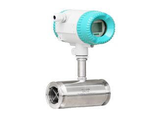
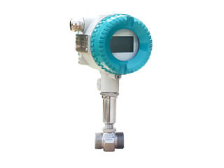
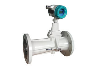
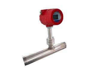
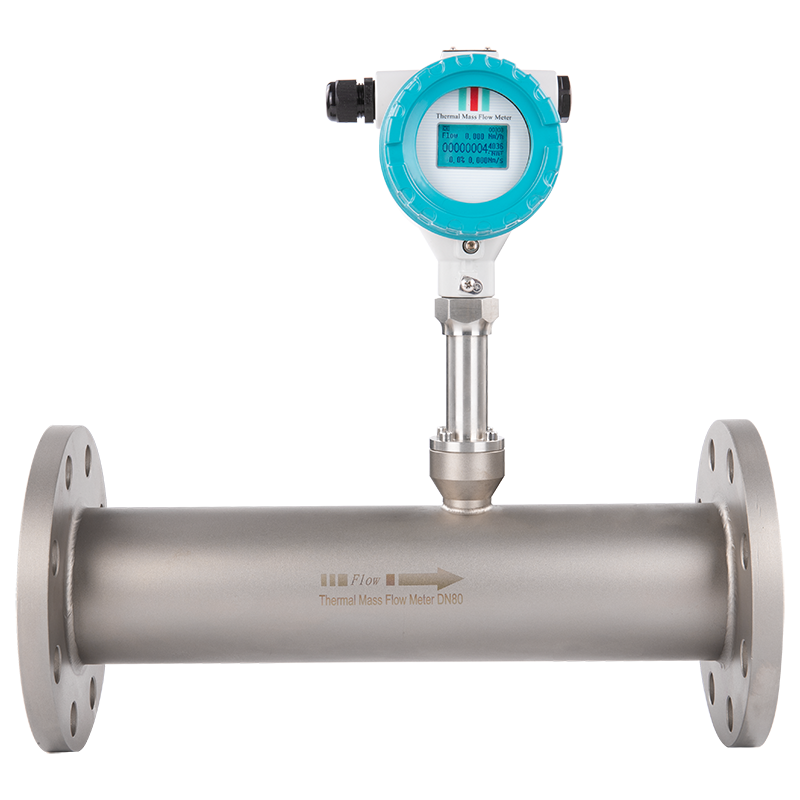
Turbine flow meter is commonly used for gas and liquid flow measurement. They have simple structure, light weight, few moving parts and easy maintenance. At the same time, it has the advantages of high precision, good stability, small pressure loss, wide range, high pressure resistance, etc., and is widely used. Our company has been selling gas turbine flowmeters and liquid turbine flowmeters for a long time, and users generally have the following problems when using turbine flowmeters.
1. No indication of normal liquid flow or no increase in total flow.
1.1 If the power supply circuit and signal circuit are open or poorly connected, use a multimeter to detect and eliminate the point of failure.
1.2 The line circuit board of the display is faulty or the connector is in poor contact. Replace the circuit board or connector.
1.3 The preamplifier is faulty. Use iron objects to move quickly at the bottom of the amplifier without signal output. Check whether the coil is disconnected or desoldered. If the amplifier is damaged, it should be replaced.
1.4 The power supply voltage is too low or unstable, increase and stabilize the power supply voltage to the specified requirements.
1.5 If the impeller is stuck and does not rotate or is damaged, the foreign matter should be removed and the damaged parts should be cleaned or replaced. After the parts are replaced, recalibration is required before use.
2. The flow rate shows gradually decreasing
2.1 The filter was clogged, then the flow rate become smaller, and the filter debris should be removed.
2.2 The valve core on the pipeline is loose and the valve opening is reduced. Repair or replace the valve.
2.3 Sundries enter the impeller or bearing, and the increase of resistance slows down the speed. Clean the flowmeter and recalibrate.
3. When the flow is zero, the flow display value is not zero or the display value is unstable
3.1 The signal wire shielding is poorly grounded, and the external electromagnetic field is interfered. Check the grounding or eliminate the on-site interference source.
3.2 Vibration of the pipeline causes the impeller to shake, strengthen the pipeline or install brackets before and after the flowmeter.
3.3 The stop valve is leaking, repair or replace the valve.
3.4 If the internal circuit board or electronic components of the display are damaged, causing interference, adopt the "short circuit method" or check one by one to find out the fault point.
4. the displayed value of the flow does not match the actual flow.
4.1 The impeller is corroded and the blade is deformed. Re-calibrate after repairing or replacing the impeller.
4.2 Sundries hinder the rotation of the impeller and remove sundries.
4.3 The output signal of the detection coil is abnormal, and the insulation resistance and conduction resistance of the coil are detected.
4.4 The fluid temperature is too high or too low, causing the gap between the bearing and the shaft to change too much.
4.5 Insufficient back pressure causes cavitation.
4.6 Due to the influence of temperature, fluid viscosity becomes larger.
4.7 No check valve is installed, and reverse flow occurs.
4.8 If the bypass valve is leaking, close the bypass valve and replace it if necessary.
4.9 The flow velocity distribution upstream of the flowmeter is distorted or pulsating flow occurs, find out the cause of the distortion or pulsating flow, and take measures to eliminate it.
4.10 If the display instrument fails, repair or replace the display instrument.
4.11 The display instrument wiring is incorrect, correct the wiring.
4.12 Display the meter setting error, correct the setting.
4.13 If the actual flow exceeds the specified flow range, replace the flowmeter with a suitable caliber.


.jpg)

.jpg)
.jpg)
.jpg)
.jpg)
.jpg)
.jpg)
.jpg)
.jpg)
.jpg)
.jpg)
.jpg)

.jpg)
.png)
.jpg)
.png)