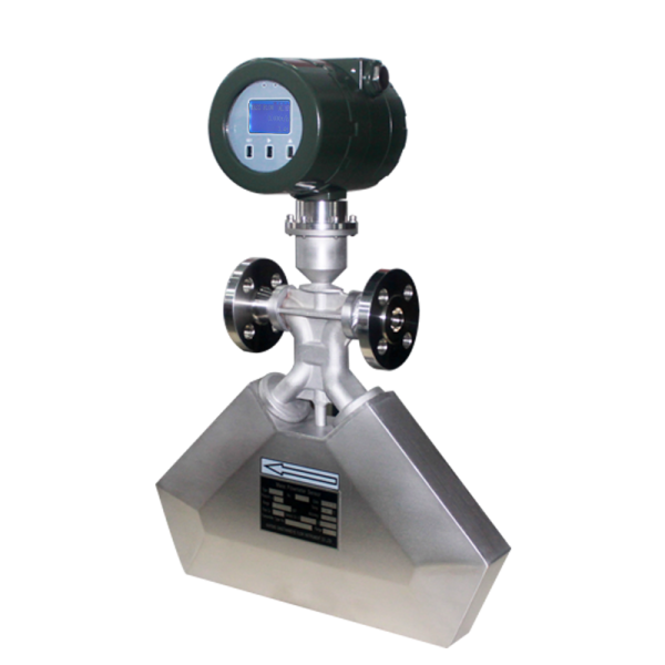
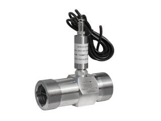
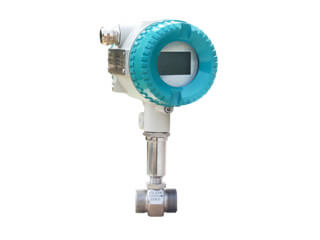
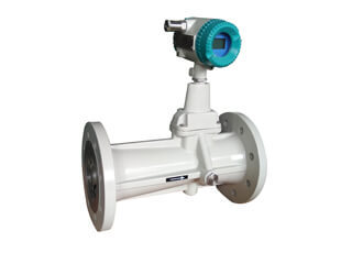
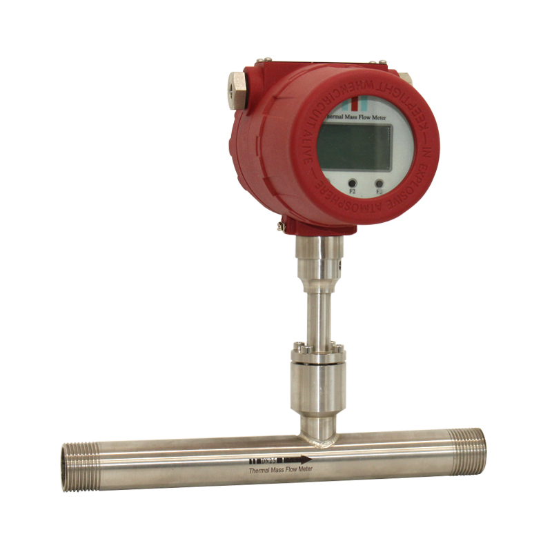
The gas turbine flow sensor is mainly composed of a casing,
a front and rear guide frame assembly, an impeller and a signal
detecting amplifier. The housing is the main part of the sensor,
the deflector, the impeller, the shaft and the bearing are housed in
the housing,and the signal sensing amplifier is mounted outside
the housing.
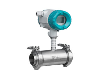
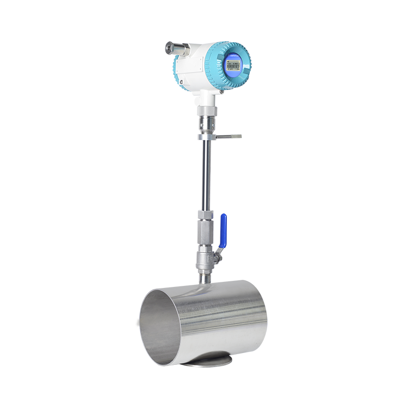
The deflector is installed at the sensor inlet and outlet. The impeller
is the sensing component of the sensor.
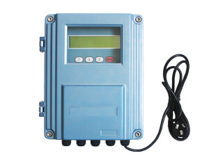
The function of the signal detection amplifier is to convert the turbo
mechanical rotation signal into an electrical pulse signal output.
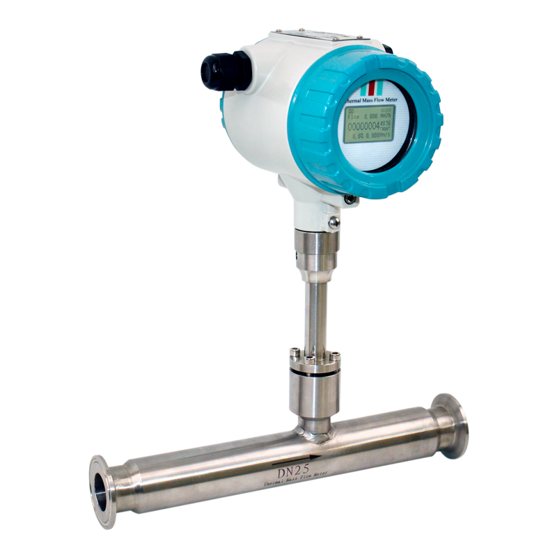
Gas turbine flowmeter works:
According to the structure of the gas turbine flowmeter, there is a tilt angle θ
between the turbine blade and the gas flow direction, and the impact force is
generated when the gas passes through the turbine flow sensor deflector,
and the impact torque to the turbine is greater than the turbo mechanical
friction torque and The sum of the flow resistance torques will drive the
turbine rotor to rotate, and the rotation speed will remain stable when all
the torques are balanced. In the flow measurement range, the flow through
the turbine is proportional to the rotational angular velocity of the turbine.
The rotational angular velocity of the turbine is measured and converted
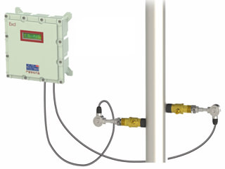
by a signal sense amplifier. As the turbine rotates, the turbine blades
cut the electromagnetic induction coils outside the wall of the tube,
periodically changing the magnetic flux through the coil to produce a
pulse signal proportional to the flow rate. The pulse signal is amplified
and shaped by the signal detection amplifier and sent to the display
instrument to display the fluid flow.


.jpg)

.jpg)
.jpg)
.jpg)
.jpg)
.jpg)

.jpg)
.jpg)
.jpg)
.jpg)
.jpg)
.jpg)

.jpg)
.png)
.jpg)
.png)