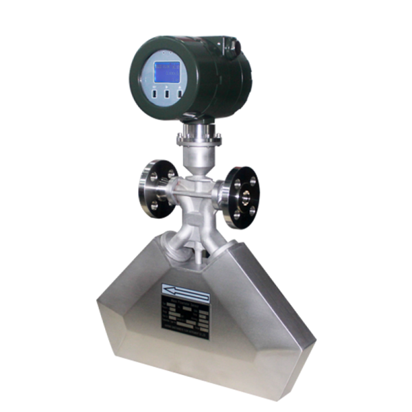
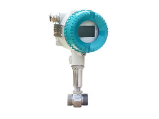
Gas turbine flow meter installation notice
For natural gas measurement, in order to better use the product when installing gas turbine flow meter on various sites, client should carefully read the product instructions.
Before installation, the pipeline needs to be purged to prevent the residual iron filings from affecting the normal operation of the flow meter.
Before installation, when the turbine is blown with a small airflow, the turbine can rotate flexibly and there is no irregular noise, so the flow meter can be installed and used.
Installation notice:
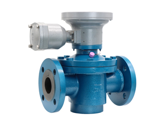
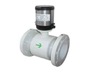
1. The gas turbine flow meter should generally be installed upright. The straight-through flow meter can be installed horizontally, vertically (flow direction should be from bottom to top when vertical) or inclined on the pipe corresponding to its nominal diameter, and make sure the flow direction of the medium is same like on the flow meter body arrow. If the straight-through flow meter needs to be installed vertically, the front cover of the flow indicator should be opened, and the panel and LCD screen should be rotated 90° to the position where the reading is. This work should be carried out by on-site technicians, or it can be handed over to the factory for modification before leaving the factory. In order to facilitate meter reading and reading, the four small screws of the continuous flow indicator and flow sensor can be removed, and then the flow meter indicator can be rotated forward or backward through 90° (or 180°) to the appropriate position, then screwed in and tighten the small screws. If the flow meter is installed outdoors, there should have shelters to prevent the sun, rain and pollution, and the installation pipe section must not have strong vibration and strong magnetic field interference.
2. In order to ensure accurate measurement, no flow regulating valve should be installed upstream. The length of the straight pipe in front of the meter should not be less than 5DN, the length of the straight pipe behind the meter should not be less than 3DN, and the flange connection type (low pressure) sealing gasket should not protrude into the pipeline. For quick-installed joints, the case and display should be removed before welding the joint.
3. Before the flowmeter is used in the newly installed pipeline, the by-pass pipeline should be used to flush the stones, sand, hemp wire, and welding slag in the pipeline. If the medium contains more impurities during use, a filter must be installed upstream to prevent impurities from damaging the electrode. The water flow area of the filter should be greater than 1.5 times the cross-sectional area of the nominal diameter.
4. When the display value of the LCD display becomes weak or the power supply voltage is lower than 2.6V, the four high-performance alkaline batteries should be changed in time. When replacing, you should open the back cover of the indicator and the battery box cover inside, take out the battery, wait for one to two minutes after the circuit is fully discharged, and then press the positive and negative signs to quickly install the new battery, so that the stored data can be displayed correctly.
5. The signal output port of the gas turbine flow meter display instrument can output the flow signal or network with the microcomputer system. When wiring, unscrew the connection port M20×1.5 hex nut and rubber sealing ring from the connection port into the inside according to the terminal mark to connect firmly, press the hex nut, and install the back cover. If it is a three-wire output, use a 6mm three-core sheathed shielded wire to connect the three cores to the three terminals of positive power, signal, and ground; if it is a two-wire output (the output is a switching signal), use 6mm The two-core sheathed shielded wire connects the two cores to the signal and ground terminals respectively.
.jpg)


.jpg)

.jpg)
.jpg)
.jpg)
.jpg)
.jpg)

.jpg)
.jpg)
.jpg)
.jpg)
.jpg)
.jpg)

.jpg)
.png)
.jpg)
.png)