Electromagnetic flow meter errors & trouble shoot
First, the liquid to be tested contains bubbles
This is a common phenomenon. There is also internal liquid inhalation and internal liquid dissolution, but the electromagnetic flowmeter can not distinguish between liquid and air bubbles, so the calculation will result in errors.
Solution:
1. It is not easy to install at the highest point of the pipeline and replace the installation position.
2. If the installation location is not easy to replace, install the air collector upstream of the flowmeter and vent it regularly.
Second, the liquid to be tested is not full
It can be said that the non-full tube is an extreme case of containing bubbles, which is not only the liquid in the tube is not full, but also contains a large number of bubbles at the top. If the liquid has not passed the electrode, the measurement result will be greatly reduced. This is a mistake in engineering design.
Solution: Pay attention to the best installation location
Third, the short circuit effect of conductive deposition
On the electrolytic cutting process test device of a diesel engine tool shop, the DN80mm meter is used to measure and control the saturated salt electrolyte flow rate to obtain the best cutting efficiency. At first, the meter was running normally. After 2 months of intermittent use, the flow rate display value was getting smaller and smaller until the flow signal was close to zero. Since the conductive material is gradually deposited, the flow signal is short-circuited. This type of fault usually does not appear during the commissioning period, but it does not appear until after a period of operation.
Solution:
The flowmeter is disassembled and the insulation layer is cleaned. Most of them are yellow rust, which is caused by the deposition of a large amount of iron oxide in the electrolyte.
Anything that starts to function normally and the traffic display becomes smaller and smaller over time should be analyzed for the possibility of such failures.
Fourth, encounter crystallization liquid selection should be cautious
A smelting plant installed a batch of electromagnetic flowmeters to measure the flow rate of the solution. Because the measuring tube of the electromagnetic flow sensor is difficult to carry out the heat insulation, a layer of crystals is formed on the inner wall and the electrode after a few weeks, resulting in a large internal resistance of the signal source. The instrument indicates that the value is abnormal. In the selection, people often encounter materials that are easy to crystallize. Although most materials can be measured normally at normal temperatures, and the catheter has a heat-insulating effect. However, the sensor measuring tube inside the flowmeter does not have this function, so the regular fluid flows through the measuring tube and causes a solid layer on the inner wall due to the temperature drop.
Solution:
1. Try to select a small flow meter for the measuring tube;
2. Disassembly is complicated and it is not recommended to select such a flow meter.
Fifth, the liquid conductivity exceeds the measurement allowable range
A chemical (smelting) plant used more than 20 sets Hastelloy B-electrode electromagnetic flowmeters to measure the higher concentration of hydrochloric acid solution, and the output signal was unstable. On-site inspection confirms that the instrument is normal and excludes other causes of interference that may cause output sloshing. However, it worked well in many other users using a Hastelloy B electrode meter to measure hydrochloric acid. Since the output impedance of the electrode is determined by the conductivity of the liquid to be measured and the size of the electrode, when the conductivity is lower than the lower limit value, the instrument cannot work normally and the indication value appears to be sloshing.
Solution:
According to the above problem, the factory works normally after replacing the tantalum electrode electromagnetic flowmeter.
1. Use other low conductivity electromagnetic flowmeters that meet the requirements, such as capacitive electromagnetic flowmeters;
2. Use other principle flowmeter, such as orifice plates.
Sixth, space electromagnetic interference
In general, if the cable between the sensor and the converter is long and there is strong electromagnetic interference around it, the cable may introduce interference signals to form common mode interference, causing display distortion, non-linearity or large sloshing.
Solution:
1. Keep away from strong magnetic fields (such as large motors, large transformers, and power cables)
2. Minimize cable length and use shielding measures
Seventh, the asymmetric flow of the liquid to be tested
Under normal circumstances, the flow rate of the fluid in the pipeline is required to be axisymmetric and the magnetic field is uniform. In practice, non-axisymmetric flow velocity distribution often occurs, and when a vortex flow occurs, an influence is exerted on the output to cause an error.
Solution:
1. There are enough straight pipe sections in the upstream to ensure that the flow velocity is distributed according to concentric circles.
2. The inner diameter of the flowmeter should be the same as the inner diameter of the pipe in a certain range of upstream and downstream, otherwise the flow velocity distribution will be uneven.
3. If the upstream straight pipe section is insufficient, the flow regulator can be installed so that it can only be partially compensated.
Eighth, installation point vibration problem
The electromagnetic flowmeter has strict requirements on the vibration of the installation point, and must be installed in a place with small vibration, otherwise it will definitely produce an error.
.jpg)


.jpg)
.jpg)
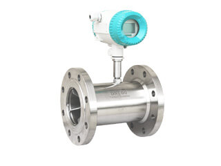
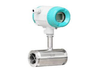
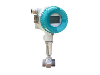
.jpg)
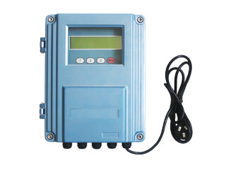
.jpg)
.jpg)
.jpg)
.jpg)
.jpg)
.jpg)
.jpg)
.jpg)
.jpg)
.jpg)
.png)
.jpg)
.png)
.jpg)